BEECN SW Portland Repeater
| BEECN Guidelines |
| Introduction |
| BEECN Program Organization |
| BEECN Sites |
| BEECN Volunteers |
| BEECN Caches |
| Operations at BEECN Sites |
| Operations at Fire Stations |
| Back to Main Guidelines ↱ |
BEECN UHF radios operate on line-of-sight. That can make comms in SW Portland's hilly neighborhoods challenging. To work around this issue, PBEM has fielded a UHF repeater in SW Portland for BEECN. The repeater is stored near Markham Elementary School, with the intention that it would be deployed in the field behind Markham ES if a crew of volunteers can access it and stand it up. The purpose of this article is to describe equipment specifications; and the deployment, set up, and demobilization of the BEECN repeater.
.jpg)
In the BEECN journaling system, the repeater is designated as the SWR1 SW Repeater. BEECN volunteers in Southwest Portland can pass radio traffic through it by setting their BEECN radios to channel 7. There are four essential parts to the BEECN repeater kit: the repeater, the antenna, the mast, and a power source.
| Relevant Documents | Updated |
|---|---|
| Icom repeater base station spec sheet | 2008 |
| BEECN repeater RFQ and purchase documents (useful for specifications) | 2014 |
| BlueSky BEECN Repeater Mast System Manual | 2016 |
Setting Up the BEECN Repeater Kit
Safety considerations
| Visual observations | MPH | Deployment conditions |
|---|---|---|
| Smoke rises vertically | < 1 | Safe |
| Wind direction shown by smoke | 1 - 3 | Safe |
| Wind felt on face, leaves rustle | 4 - 7 | Safe |
| Leaves and twigs in constant motion, wind extends light flag | 8 - 11 | Caution |
| Dust and loose paper blown freely, small branches move | 12 - 15 | Caution |
| Small trees begin to sway | 16 - 22 | Dangerous |
| Large branches in motion, wind whistles through wires | 23 - 27 | Dangerous |
| Whole trees in motion | 28 - 34 | Dangerous |
Whether for an exercise or a deployment, repeater crew members must review the following safety considerations BEFORE setting up the kit:
- Before deploying, are you safe and uninjured, and are members of your household safe and uninjured? As as is the policy for all PBEM volunteers, we do not encourage deploying if a volunteer or member of their household is injured.
- Do you have enough volunteers? It takes a minimum of three volunteers to stand up and take down the repeater kit (although, it takes only two to operate it). Two volunteers will set up the mast, and the third acts as a safety officer.
- Assess the deployment site. Is it safe to operate in the area? Are there any hazards present that could prevent volunteers from operating safely?
- Personal protective equipment (PPE). Volunteers operating the repeater should wear weather appropriate clothing and watertight footwear. Having a hardhat is VERY important, particularly as the mast is assembled and raised. Gloves are important for avoiding pinch points on the mast segments. PBEM recommends wearing a reflective vest.
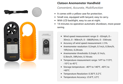
This model of anemomenter is included in the mast bag to help measure wind speed. - What is the wind doing? See table to the right. If winds are steadily blowing over 16 mph, volunteers must not attempt to assemble the mast. If the mast is up and winds pick up, the repeater crew should carefully disassemble the mast and demobilize until winds die down. There is also a handheld anemometer to measure wind speed included in the mast bag; see image to the right.
- What's over our heads? The mast should be deployed in an open field, away from trees, and completely clear of power lines. CAUTION: assume all powerlines are energized, even after an earthquake. If the mast touches a power line, repeater operators will be severely injured or killed! Never push the mast upwards if you cannot see where it is going!
- Is the mast appropriately secured? The mast kit comes with stakes for the feet and guy wires. Use them 100% of the time. This equipment helps keep the mast secure and steady.

Set up the power supply
TBA...need to document connecting up the solar panel to the batteries, as well as procedures for using a generator?
Set up the mast
- Find a spot of level ground to plant the mast. Note that it will need to be within 20 feet of the rest of the repeater equipment.
- Two volunteers will assemble the mast; the third acts as safety.
- Open the long black duffel bag on rollers and find the antenna.
- The antenna should already be affixed to a segment of mast. This is the segment that will be at the top of the mast.
- Take out the tripod base and position it. Ensure that there is not a leg pointing at the repeater (because of cables and wires).
- Fully extend the legs on the tripod out.
- Ensure that the leg braces near the top of the legs are fully depressed.
- Level the tripod with the two bubble levels located at the top of the mast base.
- Stake down the bottom of the mast using the blue stakes.
- One person should hold the mast segment with the antenna above the tripod. Another person takes the first segment of mast and slides it up through the center of the tripod, so that it connects and locks into the antenna segment.
- Continue loading in mast segments from the bottom through the tripod to raise the mast until the desired height is reached (unless there is some particular reason to do different, volunteers should assemble with all mast segments). Do not place hands where the segments meet in order to avoid a nasty pinch.
- The last mast segment should be the base segment; it has a foot similar to the feet of the tripod.
- GUY WIRES ??
- Put the silver guy wire stakes about 15 feet out. They need to be at an angle and in deep.
- Walk the guy wires out to the stakes to ensure they do not tangle as the antenna is raised. Do not tighten the guy wires into the stakes until antenna is all the way up.
- Tighten guy wires. Do not over tighten guy wires, as this will cause the antenna to pull sideways.
- Attach caution/damage tape to the guy wires to avoid tripping hazards.
- Attach the coaxial cable dangling down from the antenna to the repeater.
Repeater Kit Specifications
Repeater: Model IR3UG UHF Portable Repeater
The repeater is a Model IR3UG UHF portable UHF repeater, ruggedized for military use. PBEM purchased it from Tactical Electronics Corporation.
- Radio frequency (RF) output of 35 watts;
- Frequency range of 450 - 470 MHz.
- Site requirements: 7 m minimum antenna distance with 5 MHz frequency separation.
Comprises the following integrated as a system mounted in a Pelican enclosure:
- Repeater/base station Icom R6000TEC. Programmed on 469.5250
- 469.525 MHz TX & 464.525 MHz RX. Compliant with FCC and NTIS technical standards.
- DC power subsystem. Provides operating voltage from 120V AC, 12V DC, or solar source. Front panel metering of DC volts level.
- RF monitor subsystem. Front panel metering of RF output power. (On 4/6/2025 the meter did not appear to be working. It could have become disconnected behind the panel in which it was mounted. There is also a chance the repeater was not producing much output power although the simple communication tests done on that date seem to indicate that it was working reasonably well.)
- Duplexer. Allows the repeater to work with a single antenna. Tuned as per above frequency pair.
Physical parameters
- 20" width x 8" height x 8" depth. Weighs 42 lbs.
- Operating temperature range is 14°F to 130°F.
- MIL-STD-810F for shock, rain, vibration.
- .5 m drop.
Antenna: MaxRad Antenna
The antenna, which should be stored in the mast bag and affixed already to a segment of mast, is a portable MaxRad MFB 4505 UHF vertical 4.5dBd gain antenna. This antenna was spec'd out with the original repeater kit and includes 15 meters of connectorized coaxial cable.
Mast: BlueSky Mast AL2 Standard Series
Fully assembled, the mast is approximately 30 ft. In addition to the mast sections, the mast kit includes a tripod with a compass and levels, as well as a stake kit and primary guying to keep the mast secured to the ground.
The mast kit and antenna are stowed in a 54" x 14" x 14" wheeled carry bag for easy transport. One person can carry it with difficulty; better to have two.
Power: ZAMP Solar Generator
Output of 200 watts for charging the AGM Group 27 battery inside the DC Power subsystem. This system has two subsystems
- A pair of solar panels in a canvas case.
- A DC/AC Power Subsystem in a large black heavy metal case.
Partial instructions:
- To use the solar panels, take them out of the canvas carry case, Align them so they point at the sun and connect the cable panels' cable to the back of the DC Power subsystem. One method for aligning a solar panel is to hold a pencil or pen perpendicular to a panel and adjust the panel until the pencil has nearly no shadow. To optimize the charging ability of the panels, they should be adjusted every hour or so.
- The 12V DC can be used to power the repeater and/or charge the repeater's internal batteries. This can be accomplished by using the cable that has an automobile auxiliary power plug on each end by plugging one end into the automobile auxiliary power outlet of the subsystem and the other into the automobile auxiliary power outlet on the left side of the repeater case.
- The 120V AC is provided by an inverter mounted in the upper front of the subsystem behind the door. The 120V AC capability can be used by connecting an AC cord into the front of the inverter and ensuring that the inverter is turned on.
- The DC and AC power can be used without the solar panels but will run down the battery at a rate that will depend on the DC and AC loads. During sunny conditions the solar panels could be used to provide power to equipment as well as charge the batteries. If enough charge is provided to the battery during the day and the night-time loads are small, the battery might last until the solar panels can be used again the next day.
Repeater Kit Wish List
A couple items PBEM would like to add to the kit if resources become available:
- Handheld BEECN radio, so the repeater crew can monitor radio traffic.
- Generator/battery combo, to be used to power the repeater if needs to be deployed when the sun is low in the sky on short winter days or obscured by clouds during other seasons.
- Replace the large AGM battery inside the heavy black.
- Replace the coax for the UHF antenna with low-loss LMR 400 or equivalent.
- Upgrade the VHF radio so that it could also operate on both the 2-meter amateur band and the nearby VHF band used by Multnomah County for its quarterly VHF check-ins (MCEM 1 and MCEM 2). Each MCARES team has at least one go-kit that has this capability. Team leads participate in the quarterly check-ins along with various bureaus and at least one bridge. There is a chance that this would be mostly a matter of installing a UASI frequency template on one of the orange-box transceivers instead of the standard BEECN template.
Program/Policy Background
.jpg)
PBEM Operations purchased the repeater kit in the Spring of 2014 and it arrived at PBEM in July that year. It was tested twice, and then stored at the Jerome Sears Center. Institutional knowledge on how to use the repeater was forgotten at PBEM. A family of squirrels also took up living in the mast bag and they ate one of the instruction manuals. The repeater was moved to volunteer care in 2024 after PBEM was booted from Sears. The repeater was successfully tested again in April 2025.
Note about the mast kit: the BlueSky mast was cannibalized out of PBEM's Go-Kit program because it is superior to the mast kit spec'd with the repeater kit. The original mast was a 32 ft. tubular antenna mast in four foot sections. However, that mast included no tripod and is not as safe as the BlueSky mast.